T6C11
ELECTRONIC AND ELECTRICAL COMPONENTS · Circuit diagrams: use of schematics, basic structure; Schematic symbols of basic components
T6C11T6C →
What is component 4 in figure T-3?
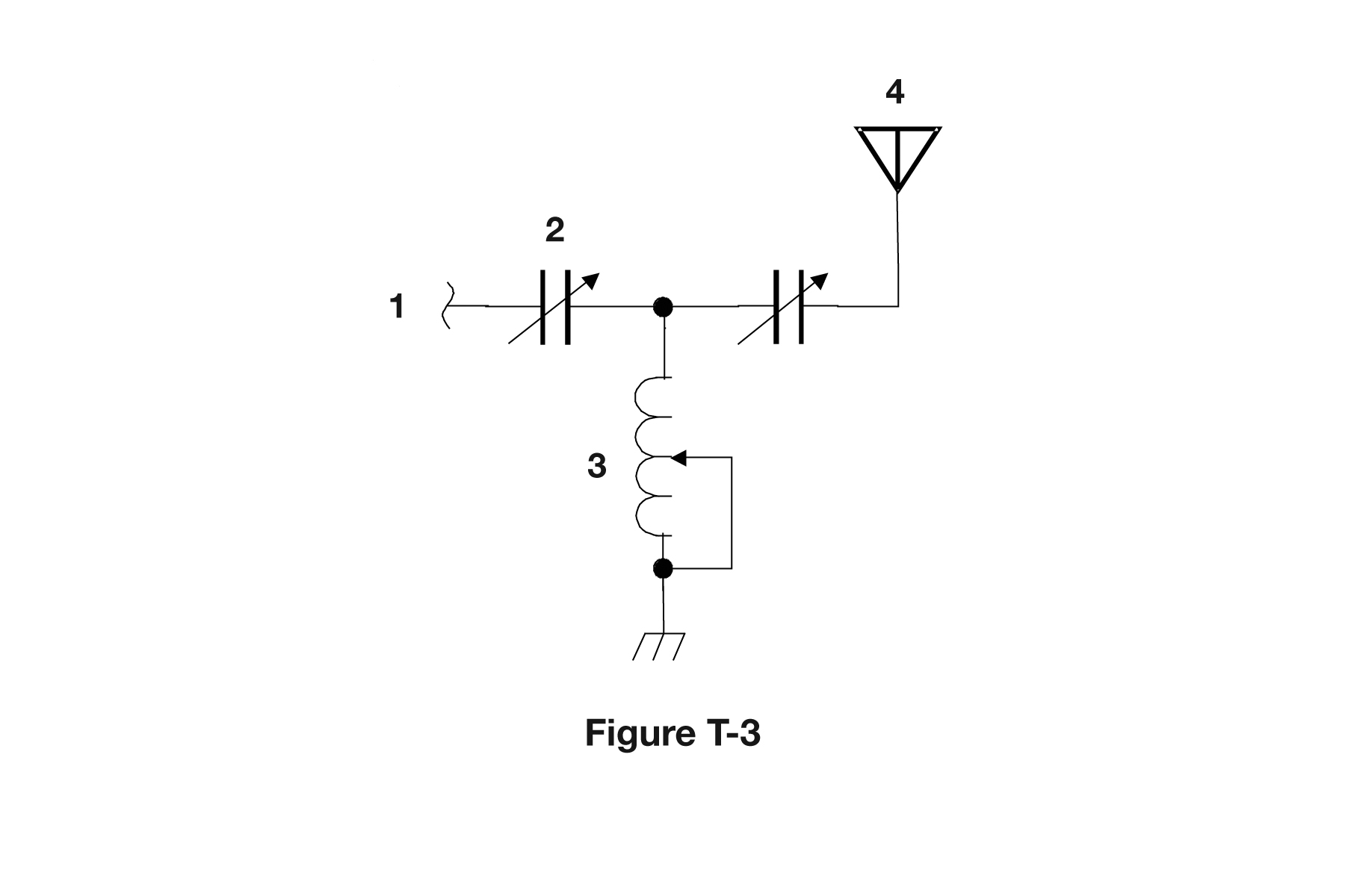
- AAntenna
- BTransmitter
- CDummy load
- DGround
Why In Figure T-3 the item labeled 4 is drawn as a vertical line topped by two diagonal lines forming an open V, which is the standard schematic symbol for an antenna. It sits at the output end of the circuit, which is where a transmitted signal is radiated. Figure T-3 is a simple transmitter chain, so the last element after the filtering and amplifying stages is the radiating element.
Watch out The ground symbol is easy to confuse with it, but ground is drawn at the bottom of a circuit as a stack of shortening horizontal bars or a solid triangle pointing down, not an open V pointing up.
Open V pointing up and out equals antenna radiating; stacked bars pointing down into the earth equals ground.
HamSandwich explanation, first draft. The question and answers are the NCVEC text.
The rest of T6C
- T6C01 What is an electrical diagram using standard component symbols called?
- T6C02 What is component 1 in figure T-1?
- T6C03 What is component 2 in figure T-1?
- T6C04 What is component 3 in figure T-1?
- T6C05 What is component 4 in figure T-1?
- T6C06 What is component 6 in figure T-2?
- T6C07 What is component 8 in figure T-2?
- T6C08 What is component 9 in figure T-2?
- T6C09 What is component 4 in figure T-2?
- T6C10 What is component 3 in figure T-3?
- T6C11 What is component 4 in figure T-3?
- T6C12 Which of the following is accurately represented in electrical schematics?