T6C06
ELECTRONIC AND ELECTRICAL COMPONENTS · Circuit diagrams: use of schematics, basic structure; Schematic symbols of basic components
T6C06T6C →
What is component 6 in figure T-2?
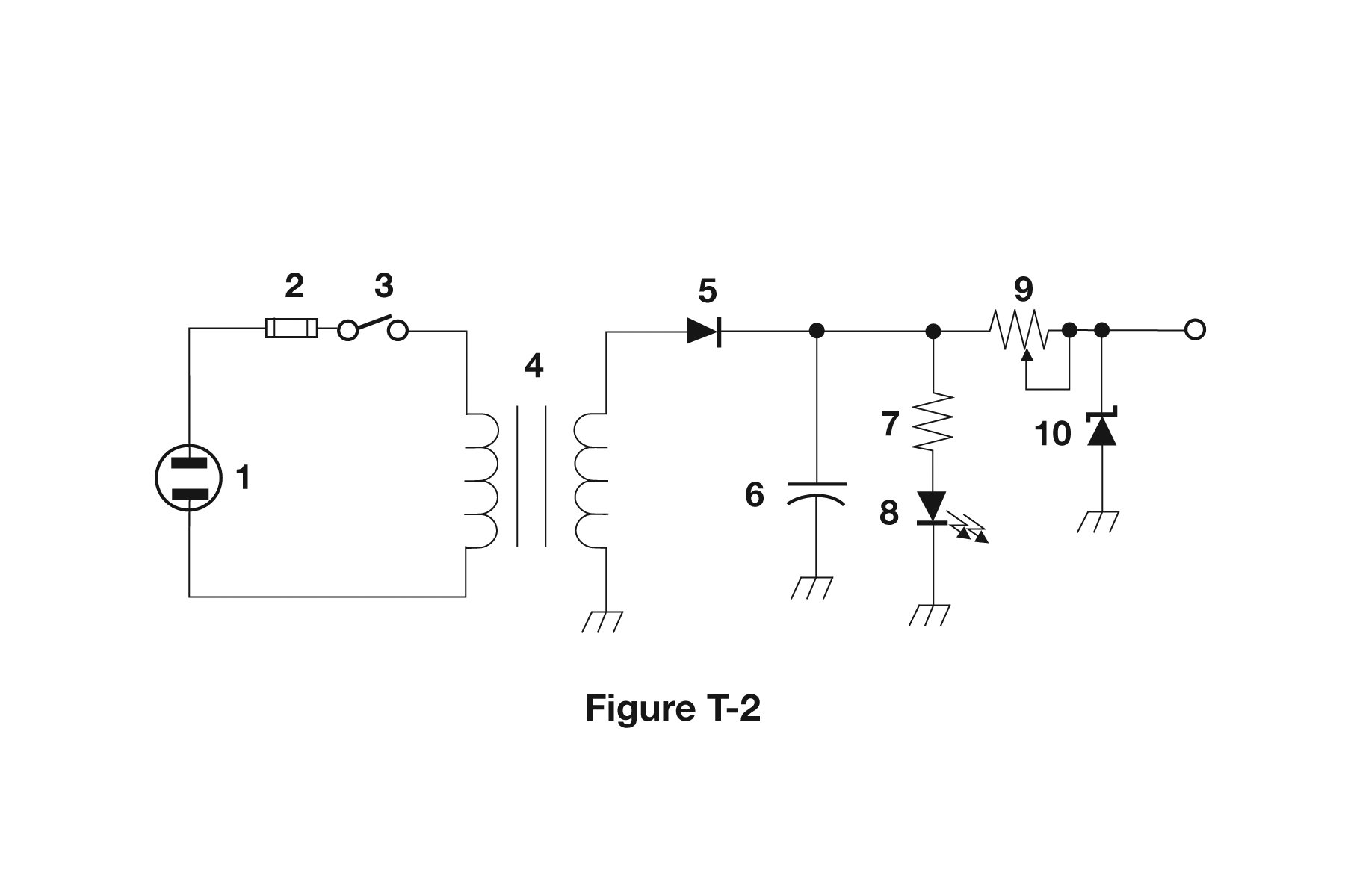
- AResistor
- BCapacitor
- CRegulator IC
- DTransistor
Why In Figure T-2 component 6 is drawn as two parallel lines facing each other with a gap between them, which is the standard schematic symbol for a capacitor. The symbol literally pictures the device: two conductive plates separated by an insulating dielectric that stores energy in an electric field. If one plate is drawn curved or the symbol has a plus sign, it is a polarized (electrolytic) capacitor, but it is still a capacitor. In this power supply diagram it sits across the output to filter, or smooth, the rectified DC.
Watch out A resistor is drawn as a zigzag (or a plain rectangle in IEC style) and a transistor shows three leads meeting a base bar inside a circle, so neither matches the two-plate symbol here.
Two parallel plates with a gap = capacitor; zigzag = resistor; coil = inductor.
HamSandwich explanation, first draft. The question and answers are the NCVEC text.
The rest of T6C
- T6C01 What is an electrical diagram using standard component symbols called?
- T6C02 What is component 1 in figure T-1?
- T6C03 What is component 2 in figure T-1?
- T6C04 What is component 3 in figure T-1?
- T6C05 What is component 4 in figure T-1?
- T6C06 What is component 6 in figure T-2?
- T6C07 What is component 8 in figure T-2?
- T6C08 What is component 9 in figure T-2?
- T6C09 What is component 4 in figure T-2?
- T6C10 What is component 3 in figure T-3?
- T6C11 What is component 4 in figure T-3?
- T6C12 Which of the following is accurately represented in electrical schematics?