T6C10
ELECTRONIC AND ELECTRICAL COMPONENTS · Circuit diagrams: use of schematics, basic structure; Schematic symbols of basic components
T6C10T6C →
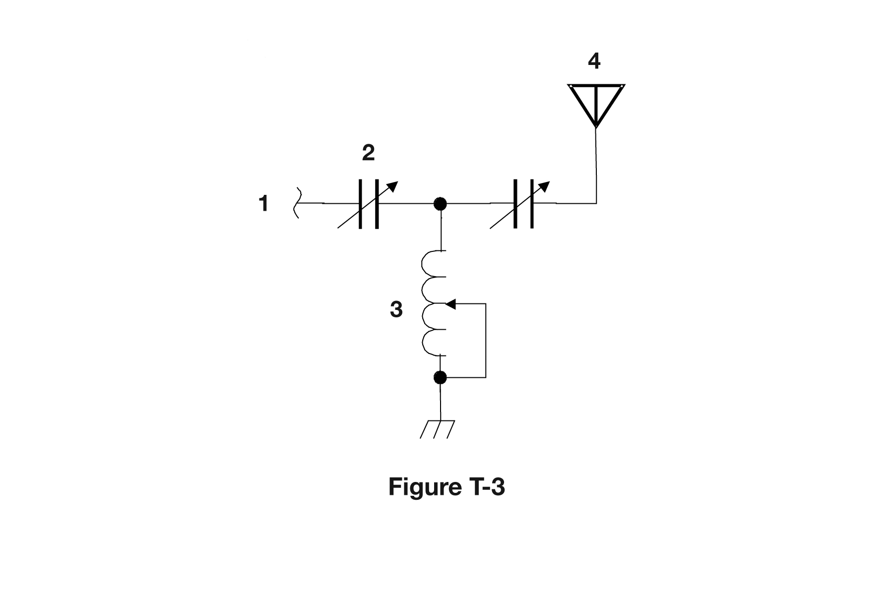
What is component 3 in figure T-3?
- AConnector
- BMeter
- CVariable capacitor
- DVariable inductor
Why In figure T-3 component 3 is drawn as a coil, a series of loops or humps along the wire, which is the schematic symbol for an inductor, and it has an arrow drawn through it meaning the value is adjustable. An arrow across any component symbol is the standard way to show that it is variable or tunable. So a coil plus an arrow is a variable inductor, the kind of tuning coil found in antenna tuners and matching networks.
Watch out The variable capacitor choice is the closest trap: a capacitor is drawn as two short parallel lines or plates, not a coil, so an arrow through plates would be the variable capacitor instead.
Loops = inductor, plates = capacitor, arrow through it = variable. Coil + arrow = variable inductor.
HamSandwich explanation, first draft. The question and answers are the NCVEC text.
The rest of T6C
- T6C01 What is an electrical diagram using standard component symbols called?
- T6C02 What is component 1 in figure T-1?
- T6C03 What is component 2 in figure T-1?
- T6C04 What is component 3 in figure T-1?
- T6C05 What is component 4 in figure T-1?
- T6C06 What is component 6 in figure T-2?
- T6C07 What is component 8 in figure T-2?
- T6C08 What is component 9 in figure T-2?
- T6C09 What is component 4 in figure T-2?
- T6C10 What is component 3 in figure T-3?
- T6C11 What is component 4 in figure T-3?
- T6C12 Which of the following is accurately represented in electrical schematics?