Study › Amateur Extra › E7D

E7D

PRACTICAL CIRCUITS

Power supplies and voltage regulators; solar array charge controllers

Drill results are kept in this browser. Log in to keep them on your account and get a study plan.

E7D011 of 15

How does a linear electronic voltage regulator work?

Why A linear regulator puts a pass element, usually a series transistor, between the raw input and the load and operates it in its linear (partially conducting) region. An error amplifier compares a sample of the output against a stable reference and continuously adjusts how hard the pass element conducts, so the voltage dropped across it changes as the input or load changes and the output stays constant. That dropped voltage times the load current is dissipated as heat, which is why linear regulators are less efficient than switchers.
Watch out The choice about duty cycle describes a switching regulator, where the control element is driven fully on and fully off and the on/off ratio sets the output; saying the pass transistor is eliminated is also backwards, since the series pass element is the heart of a linear regulator.
Linear = valve held partly open (conduction varied); switching = valve slammed on/off (duty cycle).
HamSandwich explanation, first draft. The question and answers are the NCVEC text.
E7D022 of 15

How does a switchmode voltage regulator work?

Why A switchmode (switching) regulator chops the input into a train of pulses at a high frequency and feeds them to an LC low-pass filter. The filter averages the pulse train, so the DC output is roughly the input voltage times the duty cycle. Feedback adjusts the duty cycle up or down to hold the output constant, and because the switch is either fully on or fully off it dissipates little power, giving efficiencies of 85 percent or better.
Watch out Varying the conductivity of a pass element describes a linear regulator, where a transistor acts like a variable resistor and burns off the excess voltage as heat.
Switcher = switch plus filter: output equals input times duty cycle. Linear = pass element throttled like a valve.
HamSandwich explanation, first draft. The question and answers are the NCVEC text.
E7D033 of 15

What device is used as a stable voltage reference?

Why A Zener diode operated in reverse breakdown holds a nearly constant voltage across itself over a wide range of current, so a small series resistor feeding it produces a stable reference voltage. That breakdown voltage is set during manufacture (common values like 5.1 V, 9.1 V, 12 V), and it is the sensing element most simple regulators compare their output against.
Watch out An SCR is a latching power switch used for control and crowbar protection, not a reference; the converters simply translate between digital codes and analog levels, and they in fact need an external reference such as a Zener or bandgap to work.
Zener = reverse-biased on purpose, voltage pinned. Think 'Zener holds the Zero point' for a reference.
HamSandwich explanation, first draft. The question and answers are the NCVEC text.
E7D044 of 15

Which of the following describes a three-terminal voltage regulator?

Why A three-terminal regulator such as the 78xx/79xx or LM317 family has an input pin, an output pin, and a common/ground (or adjust) pin. Inside, a pass transistor sits in series between input and output, and an error amplifier compares a sampled fraction of the output against an internal reference to control how hard that pass element conducts. Because the control element carries the load current in series with the load, it is a series regulator, and it only draws as much current as the load needs plus a small quiescent amount.
Watch out A shunt regulator, like a simple Zener or a TL431, is connected across the load and regulates by diverting excess current to ground through a dropping resistor, so it wastes current at light loads and is not how the common three-pin regulator ICs work.
Three pins: in, out, ground. The pass transistor is in line with the load, so it is a SERIES regulator.
HamSandwich explanation, first draft. The question and answers are the NCVEC text.
E7D055 of 15

Which of the following types of linear voltage regulator operates by loading the unregulated voltage source?

Why A shunt regulator sits in parallel with the load, behind a fixed series dropping resistor. It regulates by drawing (shunting) whatever extra current is needed to hold the output voltage constant, so it deliberately loads the unregulated source. A Zener diode regulator is the classic example: when load current drops, the shunt element soaks up more current, keeping total draw roughly constant.
Watch out A series regulator is the tempting pick, but it sits in line with the load and works by varying its own voltage drop, so it passes only the current the load needs rather than loading the source.
Shunt = parallel = it eats the leftover current. Series = in line = it drops the extra voltage.
HamSandwich explanation, first draft. The question and answers are the NCVEC text.
E7D066 of 15

What is the purpose of Q1 in the circuit shown in Figure E7-2?
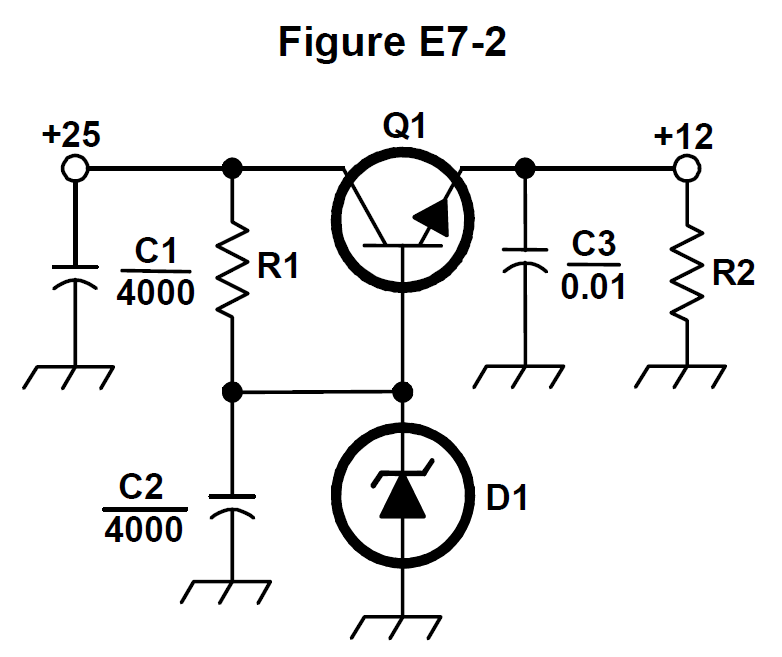
Figure E7-2 from the NCVEC question pool
Why Figure E7-2 is a classic linear series regulator: R1 feeds zener diode D1, which holds the transistor's base at a fixed reference voltage, and Q1 sits in series between the raw input and the load. Q1 acts as a variable resistance, passing whatever current the load demands while dropping the excess voltage, so the emitter (output) stays about one base-emitter drop below the zener voltage. That is why Q1 is called the series pass transistor: it regulates by adjusting current flow to hold the output voltage steady.
Watch out The 'chopping' description belongs to a switching regulator, where the pass device is driven fully on and off at high frequency and the output is filtered; in this circuit Q1 operates continuously in its linear region, not as a switch.
Q1 = series pass transistor: zener sets the reference, Q1 passes the current. Chopping means switcher, not this circuit.
HamSandwich explanation, first draft. The question and answers are the NCVEC text.
E7D077 of 15

What is the purpose of C2 in the circuit shown in Figure E7-2?

Figure E7-2 from the NCVEC question pool
Why In Figure E7-2 the zener D1 sets the reference voltage for the series pass transistor Q1, and C2 sits in parallel with that zener. A capacitor is a low impedance to AC and an open circuit to DC, so C2 shunts the leftover rectifier ripple and the zener's own noise to ground while leaving the DC reference level untouched. A cleaner reference means the regulator's output follows a steadier voltage, since the emitter of Q1 tracks the reference less one diode drop.
Watch out The brute force filter idea describes the large input capacitor right after the rectifier, which smooths the raw pulsating DC, not the small capacitor sitting across the zener reference.
Cap across the zener = ripple and noise shunt for the reference, not the main output filter.
HamSandwich explanation, first draft. The question and answers are the NCVEC text.
E7D088 of 15

What type of circuit is shown in Figure E7-2?

Figure E7-2 from the NCVEC question pool
Why Figure E7-2 shows a series pass transistor with its base held at a fixed reference by a zener diode and dropping resistor, with the load taken from the emitter. The transistor conducts continuously and drops the difference between input and output voltage as heat, so the output sits about one base-emitter drop (0.7 V) below the zener voltage. Continuous conduction with no switching element is the definition of a linear regulator.
Watch out A switching regulator would show an inductor, a catch diode and an oscillator or PWM controller chopping the input; none of those appear here. The transistor is wired as an emitter follower (common collector), not a common emitter or common base amplifier, since the output comes off the emitter and the collector ties to the raw input.
Zener plus resistor plus pass transistor, no coil = linear. See an inductor and catch diode = switching.
HamSandwich explanation, first draft. The question and answers are the NCVEC text.
E7D099 of 15

How is battery operating time calculated?

Why Battery capacity is rated in ampere-hours, which is literally current multiplied by time. Rearranging, time in hours equals amp-hours divided by the average current drawn in amperes. For example, a 10 Ah battery supplying an average 2 A lasts about 10/2 = 5 hours (less in practice, since high discharge rates and internal resistance reduce usable capacity).
Watch out Dividing current by capacity inverts the formula and gives units of 1/hours, not run time. Internal resistance plays no part in the basic capacity calculation; it affects voltage sag and efficiency under load.
Amp-hours divided by amps leaves hours. Let the units tell you which way the division goes.
HamSandwich explanation, first draft. The question and answers are the NCVEC text.
E7D1010 of 15

Why is a switching type power supply less expensive and lighter than an equivalent linear power supply?

Why A switcher chops the DC into a high frequency square wave, typically 20 kHz to several hundred kHz, before it goes through the transformer. Transformer core size (and the size of the filter inductors and capacitors that follow) is set mostly by the operating frequency: the higher the frequency, the less core material and capacitance needed for the same power. A linear supply must use a bulky iron core transformer running at the 60 Hz line frequency plus large filter capacitors, so it ends up heavier and costlier for the same output.
Watch out The claim about smaller heat sinks gets the cause backwards: switchers do run cooler, but that is because the pass devices operate fully on or fully off with high efficiency, not because the control circuitry draws less current. And a switcher definitely still needs an output filter to smooth the high frequency ripple.
Higher frequency, smaller iron. 60 Hz needs a heavy core; 100 kHz needs a tiny one.
HamSandwich explanation, first draft. The question and answers are the NCVEC text.
E7D1111 of 15

What is the purpose of an inverter connected to a solar panel output?

Why A solar panel produces direct current, but household appliances and the grid run on alternating current. An inverter is the power electronics stage that switches and shapes that DC into a sine-wave AC output at the desired voltage and frequency, typically 120 V at 60 Hz in the US. Grid-tie inverters also synchronize their output phase with the utility line.
Watch out The choice about holding voltage steady as sunlight changes describes a regulator or MPPT charge controller, and the one about preventing discharge in darkness describes the blocking diode that stops current from flowing back into the panel at night.
Invert = flip DC into AC. Diode blocks backflow, controller regulates, inverter converts.
HamSandwich explanation, first draft. The question and answers are the NCVEC text.
E7D1212 of 15

What is the dropout voltage of a linear voltage regulator?

Why A linear regulator works by acting as a variable resistance (a pass transistor) between input and output, so it can only throw away voltage, never add it. The dropout voltage is the smallest input-to-output difference the pass element needs in order to stay in its active region and keep the output regulated. Classic 7800-series parts need roughly 2 to 3 volts of headroom; low-dropout (LDO) designs get this down to a few hundred millivolts or less. If the input sags to less than output plus dropout, the output simply follows the input down and regulation is lost.
Watch out The choice about maximum output change as input varies describes line regulation, and the one about output decrease at rated load describes load regulation. Both are performance specs, not the minimum headroom requirement.
Dropout = the headroom a linear regulator needs. Input must stay above output plus dropout or the regulator 'drops out'.
HamSandwich explanation, first draft. The question and answers are the NCVEC text.
E7D1313 of 15

Which of the following calculates power dissipated by a series linear voltage regulator?

Why In a series linear regulator the pass transistor sits between input and output carrying essentially the full load current, and it drops whatever voltage the load does not use. Power in any element is voltage across it times current through it, so P = (Vin - Vout) x Iout. That is why a 12 V input feeding a 5 V, 1 A load burns 7 W of heat in the regulator and needs a heat sink.
Watch out Output voltage times output current is the useful power delivered to the load, not the waste heat in the regulator, and input voltage times input current is the total power drawn from the source (load power plus dissipation).
Only the voltage the regulator throws away gets turned into heat: P = (Vin - Vout) x I.
HamSandwich explanation, first draft. The question and answers are the NCVEC text.
E7D1414 of 15

What is the purpose of connecting equal-value resistors across power supply filter capacitors connected in series?

Why When electrolytic capacitors are stacked in series to withstand a high DC rail, their individual leakage currents differ, so without help the voltage would divide unevenly and one capacitor could exceed its rating. Equal-value resistors across each capacitor swamp that leakage and force the voltage to split evenly. The same resistor string doubles as a bleeder, draining the stored charge after the supply is switched off so the capacitors are safe to touch, and it also presents a small permanent load that keeps the supply voltage from soaring under no-load conditions.
Watch out Each single-purpose choice is true on its own, so picking just the equalizing function or just the bleeder function misses the other jobs the same resistors perform; the pool wants all three.
One resistor string, three jobs: equalize, bleed, load. When several separate answers are all true, take the all-of-these choice.
HamSandwich explanation, first draft. The question and answers are the NCVEC text.
E7D1515 of 15

What is the purpose of a step-start circuit in a high-voltage power supply?

Why Large filter capacitors in a high-voltage supply look like a dead short the instant power is applied, so the inrush current can be tens of amps and can blow fuses, damage rectifier diodes, or weld relay contacts. A step-start circuit places a resistor in series with the transformer primary for a fraction of a second, limiting that surge while the capacitors charge, then a timer or relay shorts the resistor out for normal operation. The goal is a gradual charge rather than an instantaneous current spike.
Watch out Contact arcing is a side effect of the inrush current, not the reason for the circuit; the step-start is protecting the diodes, fuses and capacitors from the surge itself. Compensating for line voltage variation is the job of a regulator or a tapped transformer, not a step-start.
Step-start = soft start: a resistor briefly tames the capacitor inrush surge, then gets shorted out.
HamSandwich explanation, first draft. The question and answers are the NCVEC text.
Nagoya NA-771 Dual Band Handheld AntennaSponsored · View on Amazon →Yaesu FT-65R VHF/UHF Dual Band HandheldSponsored · View on Amazon →
← E7C All groups E7E →