E7B11
PRACTICAL CIRCUITS · Amplifiers: class of operation; vacuum tube and solid-state circuits; distortion and intermodulation; spurious and parasitic suppression; switching-type amplifiers
E7B11E7B →
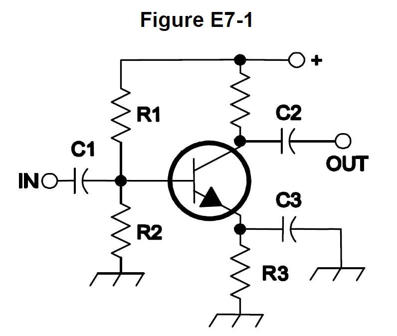
In Figure E7-1, what is the purpose of R3?
- AFixed bias
- BEmitter bypass
- COutput load resistor
- DSelf bias
Why R3 sits in the emitter leg of the transistor. Collector/emitter current flowing through it develops a voltage drop that raises the emitter above ground, which subtracts from the base-emitter forward bias. If the transistor starts to conduct harder (from heat or device variation), the larger drop across R3 pulls the bias back down, so the stage sets and stabilizes its own operating point. That degenerative action is what is meant by self bias, also called emitter bias.
Watch out Fixed bias is what the base voltage divider supplies, and emitter bypass is the job of the capacitor placed across R3 to keep the resistor from reducing AC gain.
Resistor in the emitter leg = self bias; the capacitor across it = bypass; the divider on the base = fixed bias.
HamSandwich explanation, first draft. The question and answers are the NCVEC text.
The rest of E7B
- E7B01 For what portion of the signal cycle does each active element in a push-pull, Class AB amplifier conduct?
- E7B02 What is a Class D amplifier?
- E7B03 What circuit is required at the output of an RF switching amplifier?
- E7B04 What is the operating point of a Class A common emitter amplifier?
- E7B05 What can be done to prevent unwanted oscillations in an RF power amplifier?
- E7B06 What is a characteristic of a grounded-grid amplifier?
- E7B07 Which of the following is the likely result of using a Class C amplifier to amplify a single-sideband phone s…
- E7B08 Why are switching amplifiers more efficient than linear amplifiers?
- E7B09 What is characteristic of an emitter follower (or common collector) amplifier?
- E7B10 In Figure E7-1, what is the purpose of R1 and R2?
- E7B11 In Figure E7-1, what is the purpose of R3?
- E7B12 What type of amplifier circuit is shown in Figure E7-1?