Study › Amateur Extra › E5C

E5C

ELECTRICAL PRINCIPLES

Coordinate systems and phasors in electronics: rectangular coordinates; polar coordinates; phasors; logarithmic axes

Drill results are kept in this browser. Log in to keep them on your account and get a study plan.

E5C011 of 12

Which of the following represents pure capacitive reactance of 100 ohms in rectangular notation?

Why Impedance in rectangular form is written R + jX, where the real part is resistance and the imaginary part is reactance. A pure reactance has no resistive part, so R = 0. By convention capacitive reactance is negative and inductive reactance is positive, so 100 ohms of pure capacitive reactance is 0 - j100.
Watch out The choice 0 + j100 has the right magnitude but the positive sign marks it as inductive reactance, not capacitive. The choices with 100 + j0 or 100 - j0 are 100 ohms of pure resistance with no reactance at all.
Capacitors are negative: C comes before L, and minus comes before plus. Real part first, so pure reactance starts with 0.
HamSandwich explanation, first draft. The question and answers are the NCVEC text.
E5C022 of 12

How are impedances described in polar coordinates?

Why Polar form describes a complex impedance as a vector: a length (magnitude, Z in ohms) and the angle that vector makes with the resistive axis (phase angle, in degrees). It is written as Z angle theta, for example 100 ohms at 30 degrees. The magnitude comes from the square root of R squared plus X squared, and the angle from arctangent of X divided by R.
Watch out Real and imaginary parts, or R and X values, describe the same impedance in rectangular (Cartesian) form; both forms hold the same information, they just use different axes.
Polar = how long and which way (magnitude and angle). Rectangular = how far right and how far up (R and jX).
HamSandwich explanation, first draft. The question and answers are the NCVEC text.
E5C033 of 12

Which of the following represents a pure inductive reactance in polar coordinates?

Why In polar form an impedance is written as magnitude at an angle, where the angle is set by the ratio of reactance to resistance. A pure inductance has no resistive part, so the impedance lies entirely on the +j axis of the complex plane, giving an angle of +90 degrees. This matches the physical fact that in an inductor the voltage leads the current by a quarter cycle.
Watch out A negative 90 degree angle is pure capacitive reactance, where current leads voltage; 45 degree angles occur only when resistance and reactance are equal in magnitude.
ELI the ICE man: inductor voltage leads, so L sits at +90. Any 45 degree answer means R equals X, not pure reactance.
HamSandwich explanation, first draft. The question and answers are the NCVEC text.
E5C044 of 12

What type of Y-axis scale is most often used for graphs of circuit frequency response?

Why Circuit responses can span enormous ranges, from unity gain down to a millionth of the input, so a linear vertical scale would squash all the small values against the axis. Plotting gain in decibels, which is a logarithmic measure (dB = 20 log(Vout/Vin) for voltage), compresses that range into a readable graph and turns rolloffs into straight lines with slopes like 6 dB per octave. This is the standard Bode plot format, and the horizontal frequency axis is usually logarithmic too.
Watch out A linear scale is fine for a narrow range of values, but it hides the tens of dB of attenuation in a filter stopband that engineers most want to see.
Frequency response is plotted in dB, and dB is a log unit, so the axis is logarithmic.
HamSandwich explanation, first draft. The question and answers are the NCVEC text.
E5C055 of 12

What kind of diagram is used to show the phase relationship between impedances at a given frequency?

Why A phasor diagram plots impedances (or voltages and currents) as vectors on a complex plane, with the horizontal axis for resistance (real part) and the vertical axis for reactance (imaginary part). The length of each arrow is the magnitude and the angle from the real axis is the phase, so you can see at a glance how much a reactive element leads or lags at one specific frequency. Adding impedances becomes simple vector addition on that diagram.
Watch out Near field and far field diagrams describe antenna radiation patterns at different distances, and a Venn diagram shows overlap between sets, none of which involve phase angle.
Phase relationship = phasor. The word is right there in the answer.
HamSandwich explanation, first draft. The question and answers are the NCVEC text.
E5C066 of 12

What does the impedance 50 - j25 ohms represent?

Why In rectangular notation an impedance is written R + jX, where the real part is resistance and the imaginary part is reactance. The sign of the j term tells you the type: positive j means inductive reactance, negative j means capacitive reactance. So 50 - j25 ohms is 50 ohms of resistance in series with 25 ohms of capacitive reactance.
Watch out The choice naming 25 ohms resistance with 50 ohms of reactance simply swaps the two numbers; the real part always comes first and the number attached to j is always the reactance.
Real part first, j part second. Minus j = Capacitor (think 'C' for 'cellar', below the line).
HamSandwich explanation, first draft. The question and answers are the NCVEC text.
E5C077 of 12

Where is the impedance of a pure resistance plotted on rectangular coordinates?

Why Impedance is plotted as R + jX, with resistance on the horizontal (real) axis and reactance on the vertical (imaginary) axis. A pure resistance has X = 0, so the point has no vertical component and lands somewhere along the horizontal axis (to the right of the origin for a positive resistance).
Watch out The vertical axis is where a pure reactance plots, inductive above the origin and capacitive below; a 45 degree line would mean the resistance and reactance are equal in magnitude, not that reactance is zero.
R is Real, and the real axis runs across: pure resistance sits on the horizontal line, zero j.
HamSandwich explanation, first draft. The question and answers are the NCVEC text.
E5C088 of 12

What coordinate system is often used to display the phase angle of a circuit containing resistance, inductive, and/or capacitive reactance?

Why Impedance has two parts, a size and a phase relationship between voltage and current, so it needs a two-dimensional display. Polar coordinates give exactly that: a magnitude (the impedance in ohms) and an angle measured from the resistance axis, written as something like 100 ohms at 45 degrees. Rectangular coordinates carry the same information as R + jX, and you convert between the two forms with the Pythagorean theorem and the arctangent, but the phase angle is read directly only in the polar form.
Watch out Maidenhead grid is the locator system used to describe a station's geographic location for contests and VHF work, not a circuit analysis tool; the Faraday grid and elliptical coordinates are not used for impedance at all.
Polar = magnitude at an angle. If the question mentions phase angle, think polar.
HamSandwich explanation, first draft. The question and answers are the NCVEC text.
E5C099 of 12

When using rectangular coordinates to graph the impedance of a circuit, what do the axes represent?

Why Impedance is written as a complex number Z = R + jX, where R is the resistance and X is the reactance. On a rectangular (Cartesian) graph the real part goes on the horizontal axis and the imaginary part, marked by the j operator, goes on the vertical axis. So a point plotted at (50, 25) means 50 ohms of resistance with 25 ohms of inductive reactance. Reactance below the axis (negative) is capacitive.
Watch out Magnitude and phase angle are the polar coordinate description of the same impedance, not the rectangular axes; converting between the two forms is done with the Pythagorean theorem and the arctangent.
R + jX: R is real and rides the horizontal axis, jX is imaginary and goes up and down.
HamSandwich explanation, first draft. The question and answers are the NCVEC text.
E5C1010 of 12

Which point on Figure E5-1 best represents the impedance of a series circuit consisting of a 400-ohm resistor and a 38-picofarad capacitor at 14 MHz?
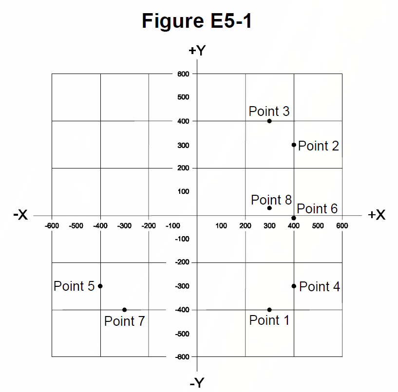
Figure E5-1 from the NCVEC question pool
Why For a series RC circuit the impedance is Z = R - jXc, so you need the capacitive reactance. Xc = 1/(2*pi*f*C) = 1/(6.2832 x 14,000,000 x 38 x 10^-12), which works out to about 300 ohms. That gives Z = 400 - j300, plotted at 400 on the resistance (horizontal) axis and 300 units below the axis because capacitive reactance is negative. That location on the chart is point 4.
Watch out The tempting trap is the mirror-image point at 400 + j300, which is what you would get from a 400-ohm resistor in series with an inductor; capacitors always plot below the real axis.
Capacitors hang down: minus j, below the axis. Inductors point up. Get R first, then Xc = 1/(2*pi*f*C).
HamSandwich explanation, first draft. The question and answers are the NCVEC text.
E5C1111 of 12

Which point in Figure E5-1 best represents the impedance of a series circuit consisting of a 300-ohm resistor and an 18-microhenry inductor at 3.505 MHz?

Figure E5-1 from the NCVEC question pool
Why Compute the inductive reactance first: XL = 2*pi*f*L = 2*pi*(3.505e6)(18e-6), which comes to about 396 ohms, essentially 400 ohms. In series the resistance and reactance add as a complex number, so Z = 300 + j396, roughly 300 + j400 ohms. On the graph that is a point 300 units to the right on the resistance axis and about 400 units up on the positive (inductive) reactance axis, which is Point 3.
Watch out The mirror-image point below the axis represents 300 - j400, a capacitive reactance, and points with the 400 and 300 swapped correspond to a different resistor and reactance pair, so check which axis carries which number.
XL = 2*pi*f*L; inductive means plot ABOVE the axis, capacitive below.
HamSandwich explanation, first draft. The question and answers are the NCVEC text.
E5C1212 of 12

Which point on Figure E5-1 best represents the impedance of a series circuit consisting of a 300-ohm resistor and a 19-picofarad capacitor at 21.200 MHz?

Figure E5-1 from the NCVEC question pool
Why For a series RC circuit the impedance is Z = R - jXc, with Xc = 1/(2*pi*f*C). Here Xc = 1/(2*pi*21.2e6*19e-12) = about 395 ohms, so Z is approximately 300 - j395 ohms. On the rectangular graph that means going right 300 units on the resistance axis and down about 400 units on the reactance axis, which is where Point 1 falls.
Watch out The point at 300 + j400 is the mirror image above the real axis, which would be a 300-ohm resistor in series with an inductor, not a capacitor; other points swap the resistance and reactance values.
Capacitors go DOWN on the graph (negative j), inductors go UP. Read R across, X up or down.
HamSandwich explanation, first draft. The question and answers are the NCVEC text.
Baofeng UV-5R Dual Band Two Way RadioSponsored · View on Amazon →Tram 1481 Dual Band Base AntennaSponsored · View on Amazon →
← E5B All groups E5D →