Study › General › G7A

G7A

PRACTICAL CIRCUITS

- Power supplies; schematic symbols

Drill results are kept in this browser. Log in to keep them on your account and get a study plan.

G7A011 of 13

What is the function of a power supply bleeder resistor?

Why A linear power supply's filter capacitors can hold a lethal charge long after the supply is unplugged. A bleeder resistor is connected permanently across the filter capacitor bank so that charge drains off through it when power is removed, typically bringing the voltage down to a safe level in seconds to a minute. It also helps stabilize the output voltage under light or no load, but its main job is safety.
Watch out Fusing against excess voltage is done by fuses, crowbar circuits or regulators, not by a resistor permanently in parallel with the capacitors. Ground loop problems are addressed by bonding and grounding practice, not by a bleeder.
Bleeder = bleeds the capacitors dry so the supply cannot bite you after you unplug it.
HamSandwich explanation, first draft. The question and answers are the NCVEC text.
G7A022 of 13

Which of the following components are used in a power supply filter network?

Why After rectification the output is a pulsating DC with ripple that must be smoothed. That is done with a low-pass filter: capacitors in shunt (parallel with the load) store charge and hold the voltage up between peaks, while inductors (chokes) in series oppose changes in current. Together they form the capacitor-input or choke-input filters found in classic supplies.
Watch out Diodes are tempting because they are in the same power supply, but they do the rectifying (converting AC to pulsating DC) that happens before the filter; the transformer changes the voltage ahead of that.
Filter = energy storage: caps hold volts, chokes hold amps. Diodes rectify, transformers transform, C and L filter.
HamSandwich explanation, first draft. The question and answers are the NCVEC text.
G7A033 of 13

Which type of rectifier circuit uses two diodes and a center-tapped transformer?

Why In a center-tapped full-wave rectifier, the transformer secondary's center tap is the return (ground) and each end of the winding feeds one diode. The two ends swing opposite in phase, so one diode conducts on each half of the AC cycle, producing two output pulses per cycle at twice the line frequency. Only two diodes are needed because the center tap provides the return path, but each half-winding only supplies half the total secondary voltage.
Watch out A full-wave bridge also gives two pulses per cycle but uses four diodes and needs no center tap; a half-wave circuit uses a single diode and conducts on only one half of each cycle.
Two diodes plus a center tap equals full-wave; four diodes with no tap equals bridge; one diode equals half-wave.
HamSandwich explanation, first draft. The question and answers are the NCVEC text.
G7A044 of 13

What is characteristic of a half-wave rectifier in a power supply?

Why A half-wave rectifier passes only one polarity of the AC input, so a single diode is all that is needed. It conducts on just one half of each input cycle, so the output ripple frequency equals the AC line frequency (60 Hz in the US), and the filter capacitor must hold up the voltage for the entire missing half cycle. That makes half-wave supplies poorer at delivering current and harder to filter than full-wave designs.
Watch out The ripple statement is backwards: a full-wave rectifier uses both halves of the cycle and so produces 120 Hz ripple, twice the half-wave's 60 Hz. Doubling the peak input voltage describes a voltage doubler circuit, not a plain half-wave rectifier.
Half-wave = one diode, 60 Hz ripple. Full-wave = two or more diodes, 120 Hz ripple.
HamSandwich explanation, first draft. The question and answers are the NCVEC text.
G7A055 of 13

What portion of the AC cycle is converted to DC by a half-wave rectifier?

Why An AC cycle is 360 degrees, with the first 180 degrees positive and the next 180 degrees negative. A half-wave rectifier uses a single diode that conducts only when the input polarity forward-biases it, so only one half of each cycle, 180 degrees, reaches the output; the other half is blocked. That is why a half-wave supply has a low, ripply output that needs heavy filtering.
Watch out The choice of 360 degrees describes a full-wave rectifier, which flips the other half cycle instead of discarding it, so the whole cycle contributes to the DC output.
Half of 360 is 180: half-wave = 180 degrees, full-wave = 360 degrees.
HamSandwich explanation, first draft. The question and answers are the NCVEC text.
G7A066 of 13

What portion of the AC cycle is converted to DC by a full-wave rectifier?

Why A full-wave rectifier uses both halves of the input waveform: the positive half passes through directly, and the negative half is inverted and delivered to the load as well. Since every part of the input cycle contributes output current, all 360 degrees of the AC cycle is converted. That is why a full-wave supply has twice the ripple frequency (120 Hz from 60 Hz mains) and is easier to filter than a half-wave supply.
Watch out The 180 degree answer describes a half-wave rectifier, which passes only one polarity and leaves the other half of the cycle blocked.
Half-wave = half a cycle = 180 degrees; full-wave = full cycle = 360 degrees.
HamSandwich explanation, first draft. The question and answers are the NCVEC text.
G7A077 of 13

What is the output waveform of an unfiltered full-wave rectifier connected to a resistive load?

Why A full-wave rectifier conducts on both halves of the AC cycle, flipping the negative half up so it becomes positive. That produces one output hump for each half cycle of the input, so with a resistive load and no filter capacitor you get DC pulses arriving at twice the input frequency. From a 60 Hz line, the ripple appears at 120 Hz.
Watch out Pulses at the same frequency as the input describe a half-wave rectifier, which throws away one half of each cycle. A steady DC voltage only appears after a filter capacitor smooths the pulses.
Full wave uses both halves: 60 Hz in, 120 Hz ripple out. Half wave keeps 60 Hz.
HamSandwich explanation, first draft. The question and answers are the NCVEC text.
G7A088 of 13

Which of the following is characteristic of a switchmode power supply as compared to a linear power supply?

Why A switchmode supply chops the DC into a high-frequency square wave, typically 20 kHz to several hundred kHz, before transforming and rectifying it. Transformer core size and filter capacitor/inductor values needed for a given power level shrink as frequency rises, because each cycle moves less energy and the core has less time to saturate. That is why a switcher delivering the same current as a 60 Hz linear supply can be a fraction of the size and weight.
Watch out The claim about fewer components is backwards: switchers need an oscillator, switching transistor, feedback/regulation circuitry and RFI filtering, so they usually have more parts than a simple transformer-rectifier-regulator linear supply. They are also noisier electrically, not inherently more stable.
Higher frequency equals smaller iron. Switchers trade 60 Hz bulk for kHz switching, plus some RF hash.
HamSandwich explanation, first draft. The question and answers are the NCVEC text.
G7A099 of 13

Which symbol in figure G7-1 represents a field effect transistor?
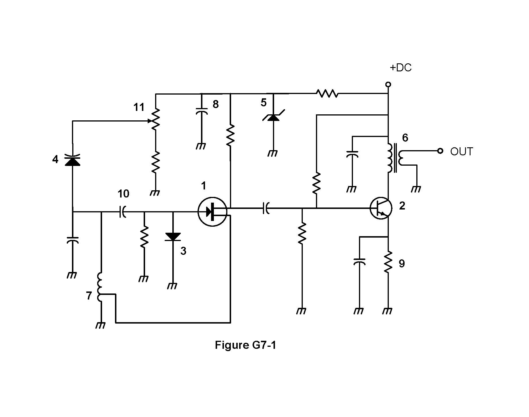
Figure G7-1 from the NCVEC question pool
Why A field effect transistor is drawn as a straight channel line with the source and drain leads coming off it at right angles, and a separate gate lead that meets the channel with an arrow on the gate. The three leads are gate, drain and source, and the gate does not touch the channel electrically, which is why the symbol shows it as a separate bar. Symbol 1 in Figure G7-1 has this gate-to-channel layout, so it is the FET.
Watch out The bipolar junction transistor symbols are the tempting ones: they show a base bar with the emitter and collector angling off it and the arrow on the emitter, not on the control lead. One of the other choices is a Zener diode, recognizable by the bent or flag-shaped cathode bar.
FET: arrow is on the gate and the leads meet the channel at right angles. BJT: arrow is on the slanted emitter.
HamSandwich explanation, first draft. The question and answers are the NCVEC text.
G7A1010 of 13

Which symbol in figure G7-1 represents a Zener diode?

Figure G7-1 from the NCVEC question pool
Why A Zener diode uses the standard diode outline, a triangle pointing at a bar, but the cathode bar has short flags bent off each end so it looks like a letter Z or a flattened S. That bent bar is the only visual clue that distinguishes it from an ordinary rectifier diode, and it signals a device meant to conduct in reverse at a fixed breakdown voltage for regulation. In figure G7-1 that triangle-with-bent-bar is the fifth symbol.
Watch out The other diode-like symbols in the figure use a plain straight cathode bar (ordinary rectifier diode) or add arrows pointing away (LED) or toward the junction (photodiode), so check the bar, not just the triangle.
Zener = bar bent like a Z. Plain straight bar is just a rectifier diode.
HamSandwich explanation, first draft. The question and answers are the NCVEC text.
G7A1111 of 13

Which symbol in figure G7-1 represents an NPN junction transistor?

Figure G7-1 from the NCVEC question pool
Why A bipolar junction transistor symbol shows a straight base bar with two leads angling off it, one of which (the emitter) carries an arrowhead. In an NPN device the emitter arrow points away from the base, out of the transistor; a PNP has that arrow pointing in toward the base. Symbol 2 in figure G7-1 is the one with the base bar and the outward-pointing emitter arrow.
Watch out Symbol 1 is the field effect transistor, whose gate lead meets a straight channel line rather than a short base bar, and Symbol 7 is a tapped inductor, a coil with a connection taken off the middle of the windings.
NPN = Not Pointing iN: the emitter arrow points out, away from the base.
HamSandwich explanation, first draft. The question and answers are the NCVEC text.
G7A1212 of 13

Which symbol in Figure G7-1 represents a solid core transformer?

Figure G7-1 from the NCVEC question pool
Why A transformer is drawn as two coils (windings) facing each other, and the core is shown by the lines drawn between them. Solid parallel lines between the windings mean a solid (iron or laminated) core, which is what Symbol 6 shows; if those lines were absent, the same two coils would be an air core transformer. The two windings indicate magnetic coupling between separate primary and secondary circuits.
Watch out The symbols showing only a single coil, including the one with a tap on it, are inductors rather than transformers, since there is no second winding to couple energy into.
Two coils = transformer; lines between them = core. No lines, air core.
HamSandwich explanation, first draft. The question and answers are the NCVEC text.
G7A1313 of 13

Which symbol in Figure G7-1 represents a tapped inductor?

Figure G7-1 from the NCVEC question pool
Why An inductor is drawn as a series of loops or half-circles (a coil), and a tapped inductor adds a third connection lead coming off a point in the middle of the winding, so the coil has three terminals instead of two. Symbol 7 is the coil with that extra center lead, which lets a circuit use only part of the total turns. Taps are common in matching networks and in transformers used for impedance selection.
Watch out A coil symbol with just two end leads is an ordinary fixed inductor, and a coil with an arrow drawn through it is a variable inductor; parallel lines beside the coil would indicate an iron core, not a tap.
Tapped inductor = coil with a third wire off the middle. Count the leads: three means tapped.
HamSandwich explanation, first draft. The question and answers are the NCVEC text.
Yaesu FT-991A HF/VHF/UHF All Mode TransceiverSponsored · View on Amazon →ARRL Ham Radio License ManualSponsored · View on Amazon →
← G6B All groups G7B →