E7G09
PRACTICAL CIRCUITS · Operational amplifiers: characteristics and applications
E7G09E7G →
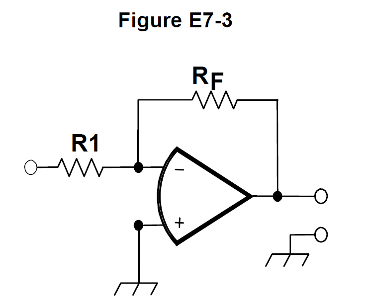
What will be the output voltage of the circuit shown in Figure E7-3 if R1 is 1,000 ohms, RF is 10,000 ohms, and 0.23 volts DC is applied to the input?
- A0.23 volts
- B2.3 volts
- C-0.23 volts
- D-2.3 volts
Why Figure E7-3 is the standard inverting op-amp configuration: the signal enters through R1 to the inverting input and RF feeds back from the output to that same node. Its voltage gain is -RF/R1, so here -10,000/1,000 = -10. Multiplying by the 0.23 V input gives -2.3 V, the minus sign meaning the output is inverted relative to the input.
Watch out The choice showing +2.3 volts has the right magnitude but ignores the polarity inversion that comes from feeding the signal into the inverting (-) input; the 0.23 volt answers would require a gain of 1, which this resistor pair does not give.
Inverting amp: gain = -RF/R1. Ratio 10k/1k = 10, flip the sign, multiply the input.
HamSandwich explanation, first draft. The question and answers are the NCVEC text.
The rest of E7G
- E7G01 What is the typical output impedance of an op-amp?
- E7G02 What is the frequency response of the circuit in E7-3 if a capacitor is added across the feedback resistor?
- E7G03 What is the typical input impedance of an op-amp?
- E7G04 What is meant by the term "op-amp input offset voltage"?
- E7G05 How can unwanted ringing and audio instability be prevented in an op-amp audio filter?
- E7G06 What is the gain-bandwidth of an operational amplifier?
- E7G07 What voltage gain can be expected from the circuit in Figure E73 when R1 is 10 ohms and RF is 470 ohms?
- E7G08 How does the gain of an ideal operational amplifier vary with frequency?
- E7G09 What will be the output voltage of the circuit shown in Figure E7-3 if R1 is 1,000 ohms, RF is 10,000 ohms, a…
- E7G10 What absolute voltage gain can be expected from the circuit in Figure E7-3 when R1 is 1,800 ohms and RF is 68…
- E7G11 What absolute voltage gain can be expected from the circuit in Figure E7-3 when R1 is 3,300 ohms and RF is 47…
- E7G12 What is an operational amplifier?